Hive Mind Framework
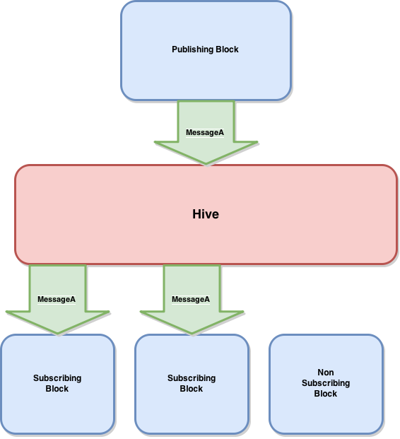
The flight control software is based on a home grown message and threading framework named Hive Mind. Hive Mind follows a publish-subscribe messaging pattern and is thread safe by design as long as the framework is followed.
Three basic types of objects exist in Hive Mind:
Blocks: Are the main work horses of Hive Mind. Each block is a thread that contains a set of instructions run in a loop. At the end of each loop iteration the thread is locked by a mutex and waits to be unlocked by the Hive. Each block has a data space saved as an incoming message queue. Blocks all register for a certain subset of messages in the system, similar to signing up for a mailing list. Messages: Messages are a simple data transportation framework for Blocks to communicate with each other. Messages contain a header with information such as:
- Message Identifier
- Endianness
- Data Size
- Sender Id

Ground Station
Software Layout
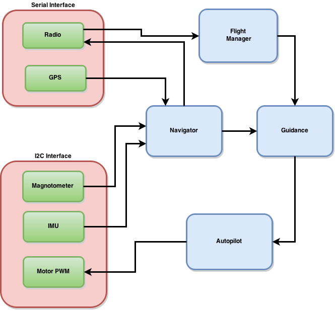
With a useable framework established a set of Blocks had to be picked that appropriately. The blocks running for the quad-copter are: I2C Interface: There are three devices on the I2C interface, however they only require one thread because they all share a common I2C Bus. The I2C Interface wakes up on an interrupt at approximately 100 Hz and reads the IMU (accelerometer/gyro) and Magnetometer. When the I2C Interface receives a blade rate command it communicates it to the PWM generator governing the motors. GPS Serial Interface: The GPS interface acts on the Rapberry Pi TTYAMA0 serial port and wakes up at 10 Hz to read messages from the GPS receiver and convert them into position data. Radio Serial Interface: The Radio serial interfaces acts on the Raspberry Pi TTYUSB0 serial port and wakes up at 100 Hz to read data from the radio. It also wakes up whenever it receives a telemetry message from the rest of the quad-copter and writes it to the radio transmit line.

Rasbpian Settings
The operating system being used to run the drone is called Raspbian . It is a port of Debian Linux for the Raspberry Pi. Getting the I2C and serial interfaces set up properly is quite simple, but only if you know what to do! Luckily the google comes to the rescue in this scenario, the following examples/instructions/tools helped me get started:
I wrote my own software to interface with the I2C, Serial and GPIO interfaces. However, there are open-source options available should you not want to be so rigorous.
