Raspberry Pi
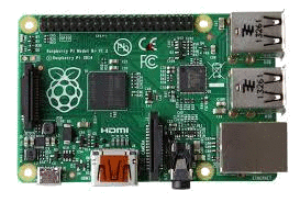
The Raspberry Pi B+ is the quad copter's main computer. The Pi boasts a 700 MHz ARM processor, 512 MB RAM and 40 GPIO ports. This system was chosen for cost, ease of access and for fun. I chose Raspbian for my operating system.
The only downside of the Pi is that it does not have a real time clock and therefore can not meet the hard real time requirements often required for flight software.
Pi Interface Card
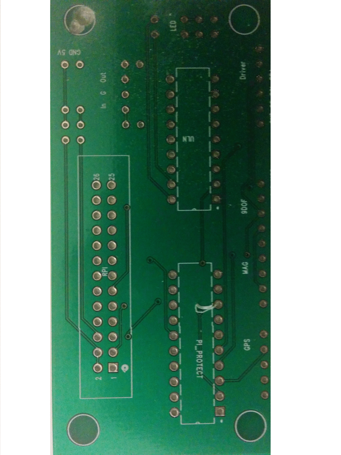
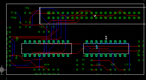
The Raspberry Pi has an interesting feature. The designers did not include protection circuits for the 40 GPIO pins. This choice was motivated by two factors. First, give the users of the Pi maximum freedom. Second, conserve cost and board real estate.
To properly protect the GPIO pins I designed a interface circuit card using Sunstone's PCB123 software . The interface card includes two integrated circuits to protect the GPIO pins, a power regulator, LEDs and a few diodes.
- ULN2803 Darlington Array
- SN54HC245 Octal Bus Transceiver
- COM00526 3.3 Volt Regulator
- Schottky Diode
- LED
The Pi takes a 5.0 V input over GPIO for power, most of the devices take a 3.3 V input, the power regulator provides a clean power source. The board also includes proper positions for capacitors on the voltage regulator if there are any power problems. The ULN2803 provides a ground side switching for the LEDs. The bus transceiver is used to protect the serial I/O lines from the Pi to the GPS receiver. Finally, the
Blade Guards
Quadcopters are dangerous,
with multiple propellers spinning at high rates they are just asking for an accident to happen.
Luckily there is a way to make it safer, blade guards.
Here is how I designed some functional and light blade guards.
First I outlined a few goals.
Based on these requirements I came up with a simple design consisting of three parts.
3d printing a structure would be ideal, however it is kind of cost restrictive. Instead, I went with the much more fun "Hardware Store" route.

Here is how I designed some functional and light blade guards.
First I outlined a few goals.
- Safety if the drone flies into someone
- No way to stick your hand into the propeller area unintentionally
- Minimal restriction of air flow
- Light weight
- Cost effective
Based on these requirements I came up with a simple design consisting of three parts.
- A "Ring" structure around the propeller
- A "Mesh" structure above the propeller
- Support material
3d printing a structure would be ideal, however it is kind of cost restrictive. Instead, I went with the much more fun "Hardware Store" route.

The "Ring"
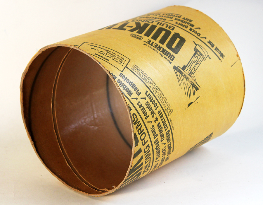
Quik-Tube is a simple cardboard tube that is used by contractors to pour cement columns. A 12 inch diameter, 4 foot length section of Quik-Tube runs about $10 at Lowes. Cut it into appropriate sections with a box cutter or small saw and you have a ring proetector.
The Cover
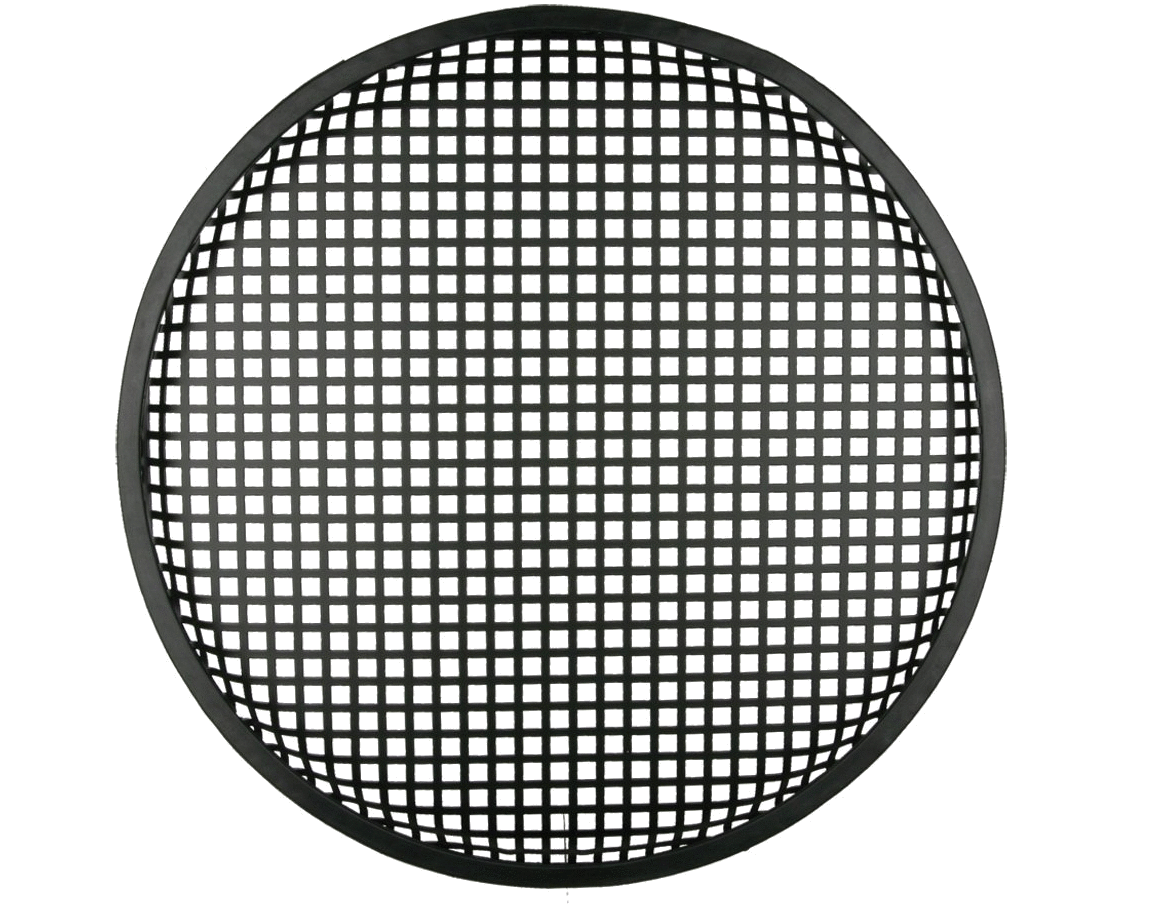
The cover is some speaker grill. It's designed to protect musician's speakers from concert goer's. It is also a great cover for your ring protector. This goes for about $5 on Amazon. Mount the cover to the ring using small wooden rods glued to the outside of the ring and several heavy duty rubber bands. This could be glued but rubber bands are removable.
Support Structure
- Right angle brackets
- Various bolts and lock nuts
- Some plastic tube. Slip this over the bolts so the threads don't eat in to the Quik-Tube
- A sturdy wooden spar
- Adhesive of choice
Waterproofing
More...coming soon!
Guidance Unit
The fully assembled Guidance Unit consists of three vertically stacked layers.
Raspberry Pi
Custom Pi Interface Card
Sensor Plate
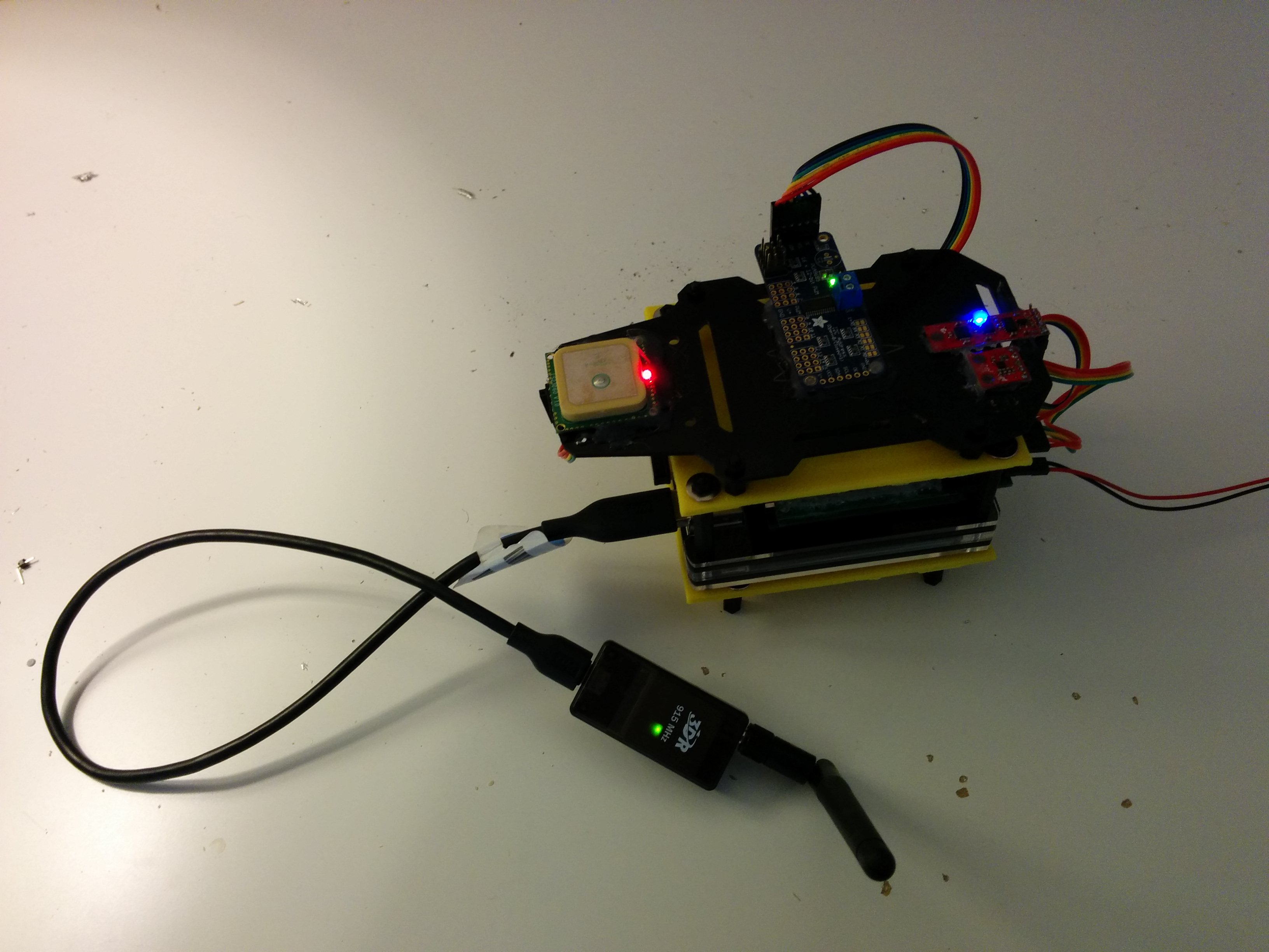 The interface card and the pi are designed to fit together through a 40 pin header. The sensor plate is attached to the pi through a 3d printed adapter bracket (the top yellow part). The entire guidance unit attaches to the body of the drone through another custom 3d printed adapter bracket.
The 3d printed brackets were designed using Free Cad
Devices
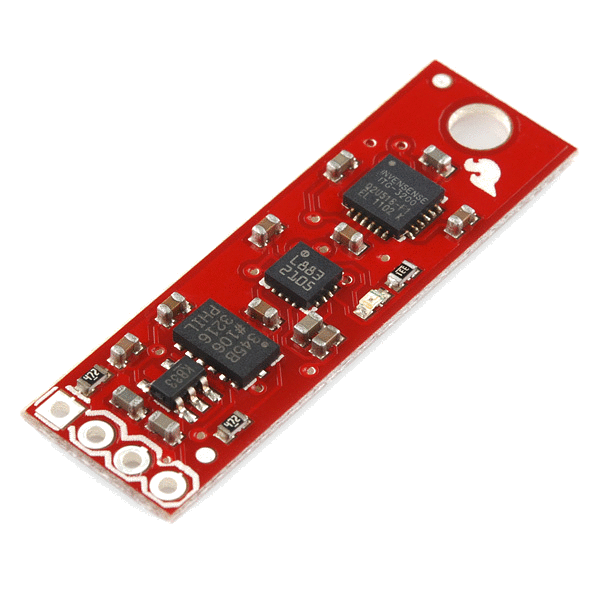
Accelerometer and Gyro
Sparkfun's 9-DOF sensor stick provides acceleration, angular velocity and magnetic field readings from the following devices:- ADXL345 Accelerometer
- HMC5883L Magnetometer
- ITG-3200 Gryo
- Interface: I2C
- Connector: 4 Pin
- Power: 3.3 Volts
- Downside: Device interrupts not broken out on board
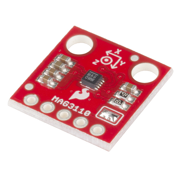
Magnetic Field Sensor
The Sparkfun MAG3110 Magnetometer is technically an extra device. The 9-DOF sensor stick has a magnetometer in it. However, the board Sparkfun packages it with has an interrupt break out we can use to practice interrupts.- Interface: I2C
- Connector: 5 Pin
- Power: 3.3 Volts
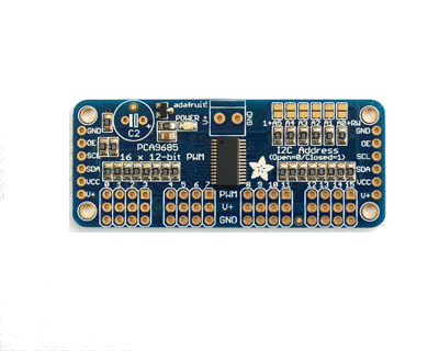
PWM Driver
Adafruit's PCA 9685 board drives up to 16 pulse width/position modulation signals which are reguired to drive ESC powering the motors.- Interface: I2C
- Connector: 6 Pin
- Power: 3.3 Volts
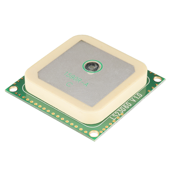
GPS Receiver
The Locosys LS20031 GPS Receiver provides position and time measurements to the drone.- Interface: Serial
- Connector: 5 Pin
- Power: 3.3 Volts
Motor
