Navigation
The Navigation algorithm calculates best estimate position, velocity and orientation by processing raw sensor inputs.
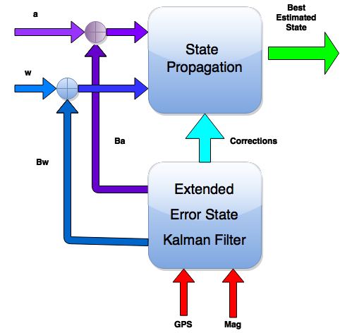
State Propagator
The accelerometer (a) and gyroscope (w) measurements are integrated at high rate to keep a continuous estimate of the state of the drone. The following states are managed by the state propagator.- Position: East-North-Up reference frame
- Velocity: East-North-Up reference frame
- Quaternion: Orientation of the drone with respect to East-North-Up frame
Kalman Filter
When available the GPS and magnetometer are incorporated using an Extended Kalman Filter (EKF). The EKF uses these measurements to calculate corrections to position, velocity and orientation as well as accelerometer (Ba) and gyroscope (Bw) biases.
Navigation Performance
More soon!
Guidance
The guidance controller is responsible for processing the measured position and velocity and calculating a desired acceleration command that will make the drone follow a desired trajectory.
This objective is achieved through use of a simple PID controller. The gains for this controller are picked based on demands of responsiveness and stability.
The stability of the system is characterized via the Nichols and Nyquist plots.
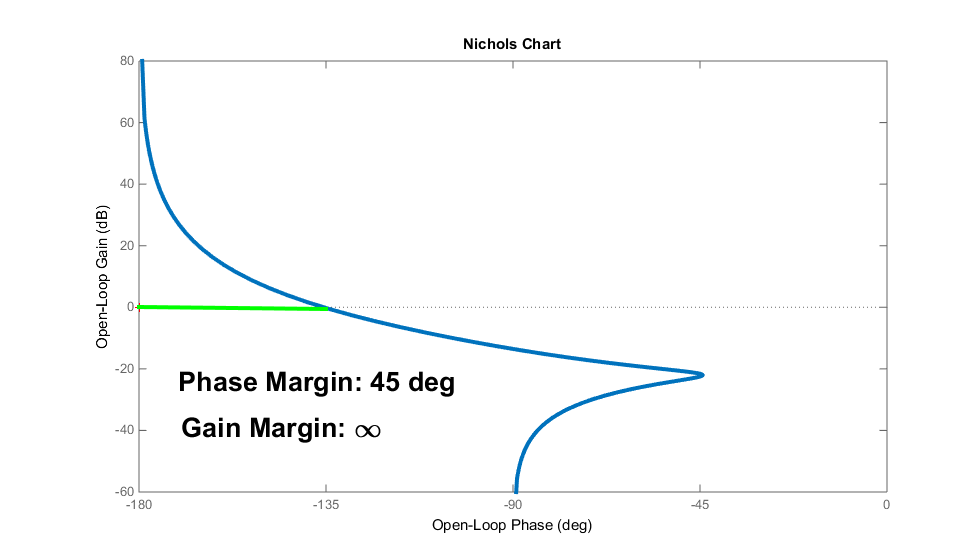
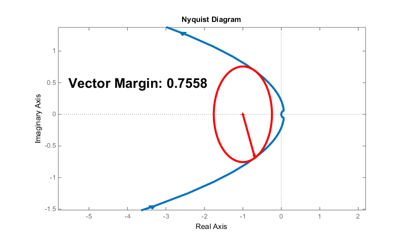
The high gain, phase and vector margins shown in these plots reveal the guidance system with robust control in terms of stability.
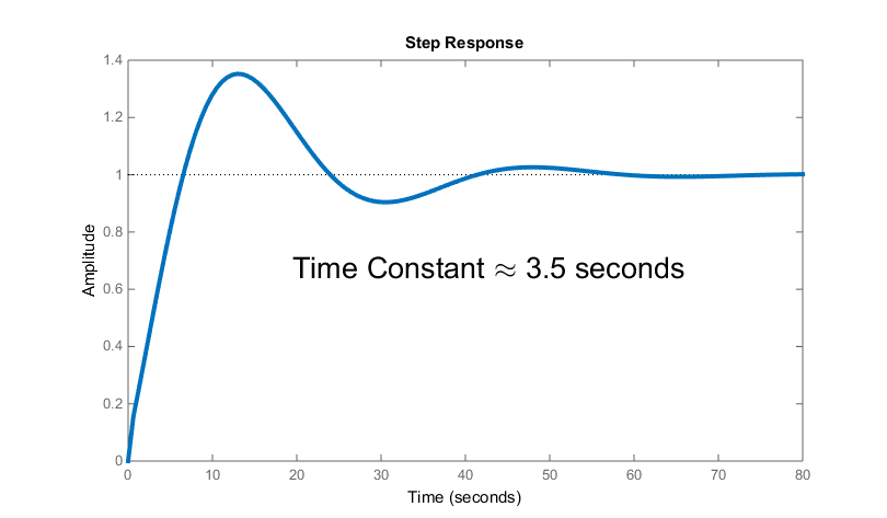
Finally, the step response of the guidance system shows a time constant on the order of 3.5 seconds. For initial testing this slower time constant is desired, as the system is tested I may retune the controller for a faster response.
Autopilot
Pitch/Roll Autopilot
Pitch and roll are controlled by an autopilot of the same design with slightly different gains. Since the drone is symmetric about the yaw axis pitch and a roll are analogous maneuvers.The pitch/roll autopilot is based on a classic Bank to Turn (BTT) Three Loop Autopilot . The stability of this autopilot is characterized in the Nichols and Nyquist plots.
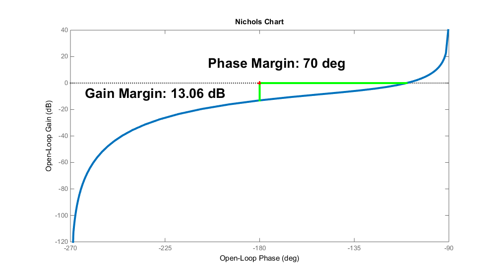
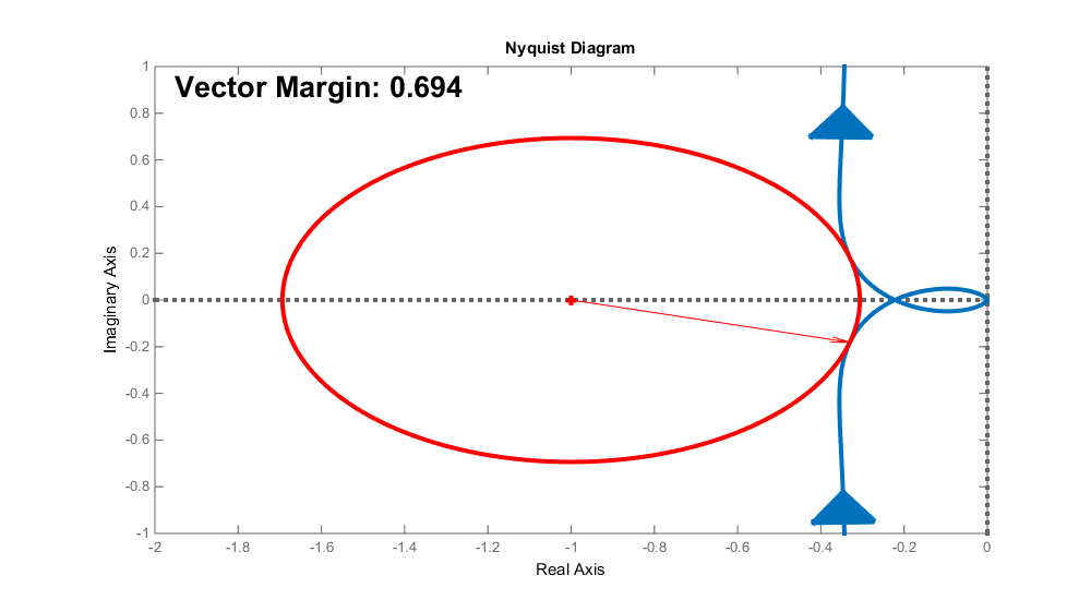
Similar to the Guidance controller, I aimed for robust stability in terms of gain, phase and vector margin.
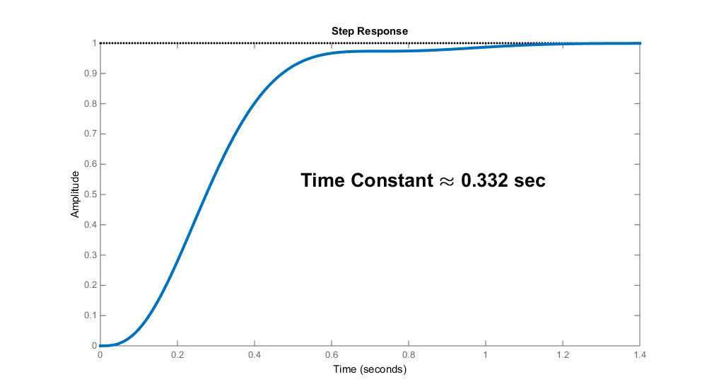 The Autopilot has a time constant of approximately 0.332 seconds. Having an autopilot time constant which is an order of magnitude lower than the guidance time constant gives the autopilot appropriate time to respond to any guidance command before the next command occurs.
Yaw Autopilot
The yaw controller is an angle tracking autopilot which follows the Three Loop Autopilot design. The stability of this autopilot is characterized in the Nichols and Nyquist plots.
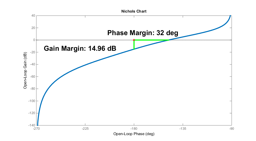
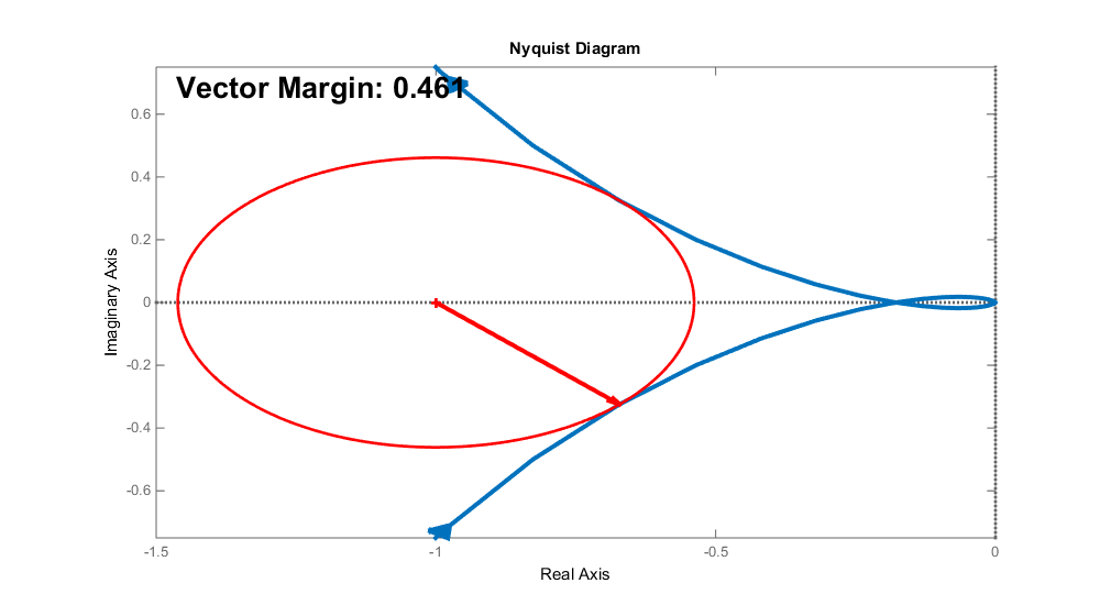
Similar to the other controllers, I aimed for robust stability in terms of gain, phase and vector margin.
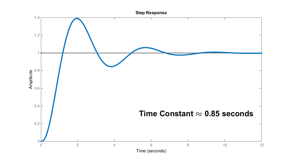 The Autopilot has a time constant of approximately 0.85 seconds. Angle error input into the integration step of this autopilot is limited in order to prevent integrator wind up and non-smooth commands. The result is the autopilot has an effective "maximum" yaw rate.
Decision Engine
All on-board decisions are made by a simple state machine shown below. The states are included in the diagram and the way state transition occurs is color coded for convenience.
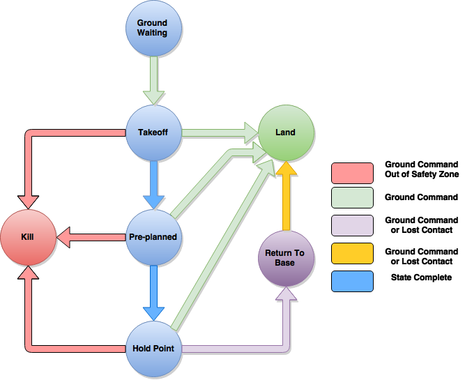
An important safety feature is the Kill state. I added this state so that if the drone leaves a pre-defined flight area, or the user commands it will immediately spin the rotors at a speed less than gravity so that it will fall to the ground. This is to prevent the drone from getting too far away if an error occurs and it is no longer navigating properly.
The other safety feature is the Return To Base and Land state. After take-off the user can execute a landing at any time from the ground station. Furthermore, if contact is lost the drone will immediately stabilize itself and fall into the Return to Base state and execute a landing when it returns.
Note
Sorry, the equations and gain values used will not be made available.